These bolts checks are common to many different connection types.
The following ASTM bolt material designations are available in RISAConnection:
Metric bolt sizes are only available when using A325M or A490M.
The material properties of metric bolts are not exactly equal to the imperial ASTM with the same designation as there is as much as a 0.5% difference between 120 or 150 ksi used in the imperial ASTMs and the 830 or 1035 MPa used in the metric ones.
When bolts are designated with a material property of A325 , the bolt strength in the ASTM varies based on the bolt diameter. Bolts up to an inch in diameter have a strength of 120 ksi, larger bolts have a strength of 105 ksi. This is enforced for the CSA S16-09 and the CSA S16-14 codes, but is NOT enforced for the AISC codes. This was ignored for AISC even though it is unconservative. That is because the larger values are given directly in AISC specification table J3.2 without regard to bolt size.
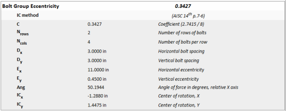
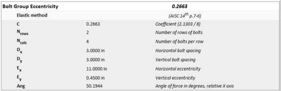
When bolt groups are subjected to shear loads that are eccentric to the centroid of the bolt group, then bolt group eccentricity is introduced. To account for this eccentricity, the AISC 14th Edition Manual provides two different methods: the Instantaneous Center of Rotation method (IC method) and the Elastic Method. These are given as options in Global Parameters - Solution tab. Information on these methods are found on pages 7-6 through 7-9 in the AISC 14th edition manual and most steel design textbooks.
The IC method is used to compute the values in Tables 7-7 through 7-14, thus program values can be compared to these tables.
Note:
Both the AISC and CSA codes give parameters when this eccentricity can be ignored for the Bolt Shear Strength check. If you wish to ignore the eccentricity when these codes allow for it make sure the Full Shear Ecc. Considered checkbox is unchecked on the Global Parameters - Solution tab.
For double angles that meet this criteria, the bolt group eccentricity coefficient can be ignored (per page 10-8 of manual):
For shear tabs that meet this criteria, the bolt group eccentricity coefficient can be ignored (per page 10-102 of manual):
For double angles that meet this criteria, the bolt group eccentricity coefficient can be ignored (per page 10-8 of manual):
For shear tabs that meet the standards of the conventional configuration, Table 10-9 is used.
From page 3-58 of the manual the eccentricity can be ignored for single row of bolts in the web-framing leg. Because the AISC manual is more detailed regarding this the 13th edition criteria are also used here.
From page 3-70 of the manual there is a discussion of how eccentricity was considered in the following table. Because there is no formal layout of parameters the AISC 13th edition was used.
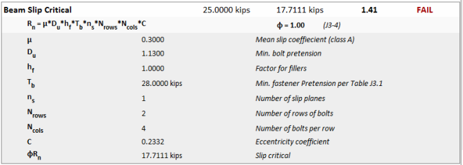
This check is calculated per equation J3-4 of the AISC 360-10 specification. The bolts can be considered slip critical if you select Slip Critical Class A or Class B listed in the Components Bolts section.
The slip critical value is multiplied by the C coefficient determined from the Center of Rotation method or the Elastic method specified in the Global Parameters. See Bolt Group Eccentricity for more information on the calculation of the C coefficient. This method was taken from the "Design of All-Bolted Extended Double Angle, Single Angle, and Tee Shear Connections" by Perry Green, Thomas Sputo, and Adam Higgins.
Slip Critical calculations are not supported for the CSA S16-09 or the CSA S16-14 design codes.
The program will use serviceability limit state for standard holes (STD) or slots transverse to the direction of load (SSLH, LSLH). The program will select required strength level if the hole is oversized (OVS) or slots are parallel to the direction of the load (SSLV, LSLV).
If the holes are defined with contradicting hole types, the program will use required strength level. For example if the beam bolts use a standard hole, and the attached clip angle uses oversized holes, required strength level will be used.
When a slip-critical connection is subjected to a tension load in addition to the shear load, the program will also calculate the ks factor per section J3.9 and apply this factor to the available slip resistance per equation J3-4.
If you have applied axial loads (compression or tension) in addition to shear loads, the required load at the beam bolts will be calculated as the resultant force created by the axial load and the shear load. This resultant force (R) will be divided by the available slip critical capacity per equation J3-4 to give the Unity Check value in the results report.
This shear capacity check is calculated per section J3.6 (shear only or shear and compression) or J3.7 (combined tension and shear) of the AISC 360-10 specification. Expand this section of the design report and RISAConnection will provide you with the exact equation, specification reference, listed variables, as well as the code check value and pass or failure notification.

Note:
If this check is part of a moment connection (End Plate or Flange Plate Moment Connection), the check will also convert the allowable shear strength to an allowable moment and check this against the user input Moment Load.

Note:
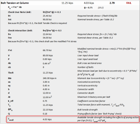
The bolt tensile capacity check is calculated for column or girder bolts in tension per section J3.7 of the AISC 360-10 specification. Expand this section of the design report and RISAConnection will provide you with the exact equation, code reference, listed variables, as well as the code check value and pass or failure notification.

This limit state includes two checks: the User Note check which will check the limit per the specification User Note in section J3.7, and the Interaction Limit check which sets upper limits on the frv (required shear stress) value. Please reference Figure C-J3.1 in the Commentary for a graphical representation of the limit.
If the User Note check determines that the check is not required, you will see the following result:

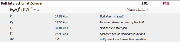
The Canadian code (CSA S16-09 or CSA S16-14) includes clause 13.12.1.4 to cover cases where bolts are subjected to combined tension and shear. This is listed as a separate check in RISAConnection as shown below: .
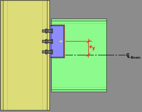
While any applied moment force is considered to be resisted by the beam flanges and not the bolts themselves, we do account for the moment due to eccentricity in this check. The eccentricities are measured between the center line of the beam and the centroid of the connecting elements, as shown below:

The procedure for calculating the worst case bolt tension caused by moment due to eccentricity is borrowed from Steel Structures: Design and Behavior, 3rd Edition by Salmon and Johnson. In this procedure, the bolt tension due to moment is added to the bolt tension caused by a pure axial force to come up with a total required force.
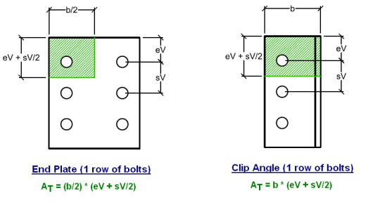
To calculate the axial load due to moment, we assume that the plate or clip angle acts as a solid rectangular beam in flexure. The flexural stress at the bolt row furthest from the center is then multiplied by the tributary area of the bolt (At). At is the maximum tributary area to a bolt at the outer-most layer, please the images below for a graphical image of this area:

Because our bolts do not connect to the extreme fiber of the connecting plate or clip angle, we use the k_eff coefficient to scale back the calculated value of Tbolt to be exactly that at the location of the bolt.
The bolt tension check will include bolt prying as long as the Bolt Prying check determines that there are prying forces in the connection. Using the default method, this is determined with the following two checks: minimum thickness and bolt strength. Alternatively, the effects of prying action can be considered using the alternative method specified on page 9-13 of the AISC 15th Edition Manual.
Default Method
The first check compares the thickness of the angle leg or plate to the tmin value per equation 9-20 of the AISC 14th Edition Manual.
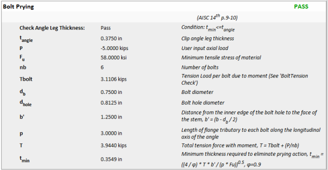
If required by the first check, the second "check" will calculate the bolt prying force. This prying force is calculated per the equation 9-28 of the AISC 14th Edition Manual. This is then used in the Bolt Tension check.

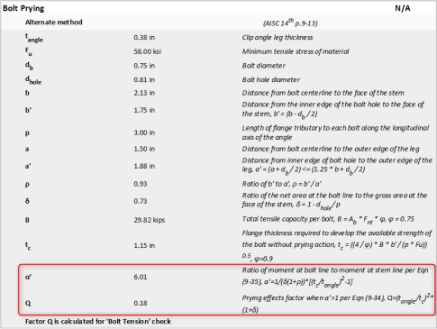
The AISC Steel Design Manual presents an alternative design approach to bolt prying on page 9-13 (AISC 15th Edition Manual). To use the alternative method, select the Reduce Avail. Bolt Strength by Prying Effects Factor Q check-box on the Solution tab of the (Global) Model Settings.
This alternative method reduces the available capacity of the bolts by the factor Q which is defined by equations 9-32, 9-33 and 9-34. The appropriate Q equation is dependent on the value of α’ which is calculated in the Bolt Prying section. The Q equation used is shown at the end of Bolt Prying section.
Q is then used to reduce the available bolt capacity at the end of the Bolt Tension at Column section.
Note:
This check is calculated per section J3.10 of the AISC 360-10 specification. Expand this section of the design report and RISAConnection will provide you with the exact equations, code reference, listed variables, as well as the code check value and pass or failure notification.
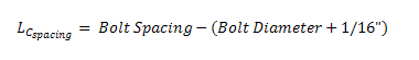
Rn_spacing and Rn_edge are taken as the minimum value of the Tear Out and Bearing calculations. These equations are reported in the variable explanation. The spacing variables Lc_edge and Lc-spacing are described below:

Note:
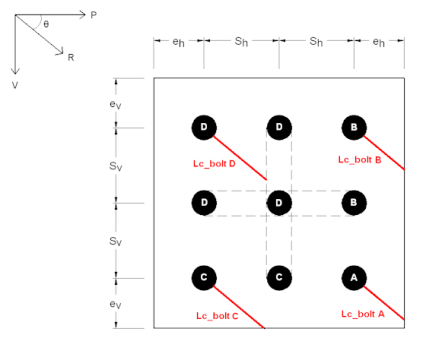
When axial load is introduced into the connection, the bolt bearing limit state check becomes much more complicated. The direction of the resultant force (axial and shear resultant) affects the direction of the bearing and RISAConnection takes this into account when calculating the edge distances.
Any given layout of bolts can consist of up to four bolt edge group distances.
Please see the image below for an example of this:
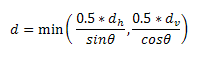
The Bolt Bearing limit state will display three bolt hole diameter values: dv, dh, and d. These allow the program to properly calculate edge distances when slotted bolt holes are present.

Therefore, if you have a standard bolt hole, dh = dv and d = 0.5*dv = 0.5*dh. But if you have a slotted hole, the program will calculate d using the following formula:
RISAConnection will calculate the individual capacity of each bolt based on their edge distance and then sum them to obtain the total bolt bearing strength.
Note:
If this check is part of a moment connection (End Plate, Flange Plate Moment Connection or Cap Plate Flange Plate Moment Connection), the check will also convert the allowable shear strength to an allowable moment and check this against the user input Moment Load.
Note: